

#ESP32 # BLE #COVID19 #Coronavirus #SocialDistancing #FlattenTheCurve #DeltaVariant #Pandemic
In this Project, We will show you how to create a Social Distancing Monitor using ESP32 Wi-Fi/BLE Controller with some LEDs and Buzzer.

Watch the Video Tutorial
You can watch the Video Tutorial by clicking the link below or continue reading the written instructions below:
Project Brief

Project Objectives

Parts Components List

Schematic Wiring Diagram
- ESP32 Controller or RGB Module has its male header pins soldered properly.
- All Jumper Wires are properly inserted in the breadboard.
- ESP32 Controller is fully inserted on the breadboard and should not have any gap between the controller & the breadboard.

Project Methodology


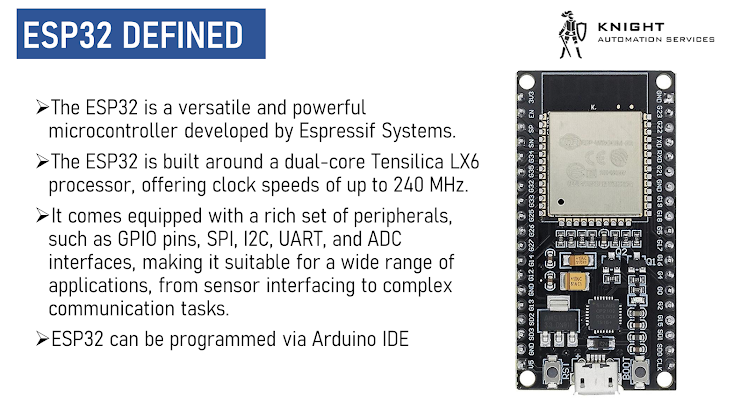
ESP32 Dev Board Controller is a highly versatile microcontroller board known for its robust capabilities.
It features the ESP32 chip, which not only offers powerful processing but also includes built-in Bluetooth Low Energy (BLE) functionality.
This BLE capability makes it well-suited for a wide range of applications, particularly in the realm of IoT and wearables. Developers can leverage the ESP32's BLE capabilities to create energy-efficient and wireless connections between devices, making it a popular choice for projects that require both Wi-Fi and BLE connectivity.
In summary, the ESP32 Dev Board Controller's integration of BLE enhances its potential for IoT and wireless communication applications.


- RGB LED remains OFF
- Buzzer remains OFF

- RGB LED blinks GREEN
- Buzzer remains OFF

- RGB LED blinks YELLOW
- Buzzer remains OFF

- RGB LED blinks RED
- Buzzer turns ON

Arduino IDE 2.0 ESP32 Board Installation


E) Now go to Tools and then click Board, you will see ESP32, click on that and it will expand all the ESP32 variants. For this project we will select ESP32 Dev Module

/*  Knight Automation Services  Blink Example Sketch Modified for ESP32 Dev Board    Permission is hereby granted, free of charge, to any person obtaining a copy  of this software and associated documentation files.    The above copyright notice and this permission notice shall be included in all  copies or substantial portions of the Software.
  Blink Example Sketch Modified from   https://www.arduino.cc/en/Tutorial/BuiltInExamples/Blink*/
#define LED_BUILTIN 2
// the setup function runs once when you press reset or power the boardvoid setup() {  // initialize digital pin LED_BUILTIN as an output.  pinMode(LED_BUILTIN, OUTPUT);}
// the loop function runs over and over again forevervoid loop() {  digitalWrite(LED_BUILTIN, HIGH);  // turn the LED on (HIGH is the voltage level)  delay(1000);                      // wait for a second  digitalWrite(LED_BUILTIN, LOW);   // turn the LED off by making the voltage LOW  delay(1000);                      // wait for a second}


Arduino IDE 2.0 Code
/*   Based on Neil Kolban example for IDF: https://github.com/nkolban/esp32-snippets/blob/master/cpp_utils/tests/BLE%20Tests/SampleScan.cpp   Ported to Arduino ESP32 by Evandro Copercini   Modifed by Knight Automation Services for ESP32 Social Distancing Monitor
  Permission is hereby granted, free of charge, to any person obtaining a copy  of this software and associated documentation files.    The above copyright notice and this permission notice shall be included in all  copies or substantial portions of the Software.*/
/////////////////////////////////////////////////////// LIBRARIES ////////////////////////////////////////////////////////////////
#include <BLEDevice.h>#include <BLEUtils.h>#include <BLEScan.h>#include <BLEAdvertisedDevice.h>#include <BLEServer.h>

/////////////////////////////////////////////////////// CONFIGURATIONS ////////////////////////////////////////////////////////////////
int Very_Close_Proximity_RSSI_Threshold = -70;int Moderate_Proximity_RSSI_Threshold = -80;int Far_Proximity_RSSI_Threshold = -85;
/////////////////////////////////////////////////////// CONNECTIONS ////////////////////////////////////////////////////////////////
int RGB_LED_R_Pin = 25;  //4int RGB_LED_G_Pin = 26;  //4int RGB_LED_B_Pin = 27;  //4int Buzzer_Pin = 5;
/////////////////////////////////////////////////////// LOGICAL OPERATIONS ////////////////////////////////////////////////////////////////
int scanTime = 5;  //In secondsBLEScan *pBLEScan;int RSSI_STS = 0;int LED_BUZZER_FREQUENCY = 0;
unsigned long previousMillis = 0;   // will store last time LED was updatedunsigned long previousMillis2 = 0;  // will store last time LED was updatedunsigned long previousMillis3 = 0;  // will store last time LED was updated
int LED_STATE = 0;


/////////////////////////////////////////////////////// BLE VARIABLES ////////////////////////////////////////////////////////////////


BLEClient *pClient;bool deviceFound = false;
String knownAddresses[] = { ":  :  :  :  :  ", " :  :  :  :  : " };
String knownNames[] = { ":  :  :  :  :  ", "ESP32_SDM" };
static BLEAddress *pServerAddress;
std::string pServerName;
#define SERVICE_UUID "4fafc201-1fb5-459e-8fcc-c5c9c331914b"#define CHARACTERISTIC_UUID "beb5483e-36e1-4688-b7f5-ea07361b26a8"

static void notifyCallback(  BLERemoteCharacteristic *pBLERemoteCharacteristic,  uint8_t *pData,  size_t length,  bool isNotify) {  Serial.print("Notify callback for characteristic ");  Serial.print(pBLERemoteCharacteristic->getUUID().toString().c_str());  Serial.print(" of data length ");  Serial.println(length);}
class MyAdvertisedDeviceCallbacks : public BLEAdvertisedDeviceCallbacks {  /**         Called for each advertising BLE server.    */  void onResult(BLEAdvertisedDevice advertisedDevice) {    Serial.printf("Advertised Device: %s \n", advertisedDevice.toString().c_str());    pServerAddress = new BLEAddress(advertisedDevice.getAddress());    pServerName = advertisedDevice.getName();
    Serial.print("Name =  ");    Serial.println(pServerName.c_str());
    bool known = false;    bool known2 = false;    for (int i = 0; i < (sizeof(knownAddresses) / sizeof(knownAddresses[0])); i++) {      if (strcmp(pServerAddress->toString().c_str(), knownAddresses[i].c_str()) == 0) known = true;    }
    for (int i = 0; i < (sizeof(knownNames) / sizeof(knownNames[0])); i++) {      if (strcmp(pServerName.c_str(), knownNames[i].c_str()) == 0) known2 = true;    }    Serial.print("known2: ");    Serial.println(known2);
    if (known2) {      Serial.print("Device found: ");      Serial.println(advertisedDevice.getRSSI());      RSSI_STS = (advertisedDevice.getRSSI());      if (advertisedDevice.getRSSI() > -150) deviceFound = true;      else deviceFound = false;      Serial.println(pServerAddress->toString().c_str());      advertisedDevice.getScan()->stop();    } else {      deviceFound = false;    }    /******** This releases the memory when we're done. ********/    delete pServerAddress;  }};
void setup() {  Serial.begin(115200);  Serial.println("Scanning...");
  Pin_Mode_Configurations();  BLE_Setup_Stage();}
void loop() {  // put your main code here, to run repeatedly:
  unsigned long currentMillis = millis();
  if (currentMillis - previousMillis >= 2000) {    // save the last time you blinked the LED    previousMillis = currentMillis;
    BLEScanResults foundDevices = pBLEScan->start(scanTime, false);    Serial.print("Devices Nos: ");    Serial.println(foundDevices.getCount());    Serial.println("Scan done!");    pBLEScan->clearResults();  // delete results fromBLEScan buffer to release memory  }
  if (currentMillis - previousMillis2 >= 2000) {    // save the last time you blinked the LED    previousMillis2 = currentMillis;    Serial.print("deviceFound STS ");    Serial.println(deviceFound);
    Serial.print("RSSI_STS : ");    Serial.println(RSSI_STS);
    if (RSSI_STS > Very_Close_Proximity_RSSI_Threshold) {      Serial.println("Very Close Proximity");    } else if ((RSSI_STS <= Very_Close_Proximity_RSSI_Threshold && RSSI_STS > Moderate_Proximity_RSSI_Threshold)) {      Serial.println("Moderate Proximity");
    } else if (RSSI_STS <= Far_Proximity_RSSI_Threshold) {      Serial.println("Far Proximity");    }  }

  if (deviceFound) {    if (RSSI_STS > Very_Close_Proximity_RSSI_Threshold) {      // Serial.println("Very Close Proximity");
      unsigned long currentMillis2 = millis();      if (currentMillis2 - previousMillis3 >= 150) {  // ON Period        // save the last time you blinked the LED        previousMillis3 = currentMillis2;
        if (LED_STATE == 1) {
          digitalWrite(RGB_LED_R_Pin, HIGH);          digitalWrite(RGB_LED_G_Pin, LOW);          digitalWrite(RGB_LED_B_Pin, LOW);          digitalWrite(Buzzer_Pin, HIGH);          LED_STATE = 0;        } else if (LED_STATE == 0) {          digitalWrite(RGB_LED_R_Pin, LOW);          digitalWrite(RGB_LED_G_Pin, LOW);          digitalWrite(RGB_LED_B_Pin, LOW);          digitalWrite(Buzzer_Pin, LOW);          LED_STATE = 1;        }      }

    } else if ((RSSI_STS <= Very_Close_Proximity_RSSI_Threshold && RSSI_STS > Moderate_Proximity_RSSI_Threshold)) {      // Serial.println("Moderate Proximity");      unsigned long currentMillis2 = millis();
      if (currentMillis2 - previousMillis3 >= 500) {  // ON Period        // save the last time you blinked the LED        previousMillis3 = currentMillis2;        if (LED_STATE == 1) {          digitalWrite(RGB_LED_R_Pin, HIGH);          digitalWrite(RGB_LED_G_Pin, HIGH);          digitalWrite(RGB_LED_B_Pin, LOW);          digitalWrite(Buzzer_Pin, LOW);          LED_STATE = 0;        } else if (LED_STATE == 0) {          digitalWrite(RGB_LED_R_Pin, LOW);          digitalWrite(RGB_LED_G_Pin, LOW);          digitalWrite(RGB_LED_B_Pin, LOW);          digitalWrite(Buzzer_Pin, LOW);          LED_STATE = 1;        }      }    } else if (RSSI_STS <= Far_Proximity_RSSI_Threshold) {      // Serial.println("Far Proximity");
      unsigned long currentMillis2 = millis();
      if (currentMillis2 - previousMillis3 >= 1000) {  // ON Period        // save the last time you blinked the LED        previousMillis3 = currentMillis2;        if (LED_STATE == 1) {          digitalWrite(RGB_LED_R_Pin, LOW);          digitalWrite(RGB_LED_G_Pin, HIGH);          digitalWrite(RGB_LED_B_Pin, LOW);          digitalWrite(Buzzer_Pin, LOW);          LED_STATE = 0;        } else if (LED_STATE == 0) {          digitalWrite(RGB_LED_R_Pin, LOW);          digitalWrite(RGB_LED_G_Pin, LOW);          digitalWrite(RGB_LED_B_Pin, LOW);          digitalWrite(Buzzer_Pin, LOW);          LED_STATE = 1;        }      }    }
  } else {    // Serial.println("NO! Proximity");    RSSI_STS = -110;    digitalWrite(RGB_LED_R_Pin, LOW);    digitalWrite(RGB_LED_G_Pin, LOW);    digitalWrite(RGB_LED_B_Pin, LOW);    digitalWrite(Buzzer_Pin, LOW);  }}

void Pin_Mode_Configurations() {
  pinMode(Buzzer_Pin, OUTPUT);  pinMode(RGB_LED_R_Pin, OUTPUT);  pinMode(RGB_LED_G_Pin, OUTPUT);  pinMode(RGB_LED_B_Pin, OUTPUT);}

void BLE_Setup_Stage() {
  BLEDevice::init("ESP32_SDM");
  BLEServer *pServer = BLEDevice::createServer();  BLEService *pService = pServer->createService(SERVICE_UUID);  BLECharacteristic *pCharacteristic = pService->createCharacteristic(    CHARACTERISTIC_UUID,    BLECharacteristic::PROPERTY_READ | BLECharacteristic::PROPERTY_WRITE);
  pCharacteristic->setValue("Hello World says Neil");  pService->start();  // BLEAdvertising *pAdvertising = pServer->getAdvertising();  // this still is working for backward compatibility  BLEAdvertising *pAdvertising = BLEDevice::getAdvertising();  pAdvertising->addServiceUUID(SERVICE_UUID);  pAdvertising->setScanResponse(true);  pAdvertising->setMinPreferred(0x06);  // functions that help with iPhone connections issue  pAdvertising->setMinPreferred(0x12);  BLEDevice::startAdvertising();  Serial.println("Characteristic defined! Now you can read it in your phone!");


  pBLEScan = BLEDevice::getScan();  //create new scan  pBLEScan->setAdvertisedDeviceCallbacks(new MyAdvertisedDeviceCallbacks());  pBLEScan->setActiveScan(true);  //active scan uses more power, but get results faster  pBLEScan->setInterval(100);  pBLEScan->setWindow(99);  // less or equal setInterval value}

Code Explanation
/////////////////////////////////////////////////////// LIBRARIES ////////////////////////////////////////////////////////////////
#include <BLEDevice.h>#include <BLEUtils.h>#include <BLEScan.h>#include <BLEAdvertisedDevice.h>#include <BLEServer.h>/////////////////////////////////////////////////////// CONFIGURATIONS ////////////////////////////////////////////////////////////////
int Very_Close_Proximity_RSSI_Threshold = -70;int Moderate_Proximity_RSSI_Threshold = -80;int Far_Proximity_RSSI_Threshold = -85;
/////////////////////////////////////////////////////// CONNECTIONS ////////////////////////////////////////////////////////////////
int RGB_LED_R_Pin = 25; //4int RGB_LED_G_Pin = 26; //4int RGB_LED_B_Pin = 27; //4int Buzzer_Pin = 5;/////////////////////////////////////////////////////// BLE VARIABLES ////////////////////////////////////////////////////////////////
BLEClient *pClient;bool deviceFound = false;
String knownAddresses[] = { ": : : : : ", " : : : : : " };
String knownNames[] = { ": : : : : ", "ESP32_SDM" };
static BLEAddress *pServerAddress;
std::string pServerName;
#define SERVICE_UUID "4fafc201-1fb5-459e-8fcc-c5c9c331914b"#define CHARACTERISTIC_UUID "beb5483e-36e1-4688-b7f5-ea07361b26a8"void setup() { Serial.begin(115200); Serial.println("Scanning...");
Pin_Mode_Configurations(); BLE_Setup_Stage();}void Pin_Mode_Configurations() {
pinMode(Buzzer_Pin, OUTPUT); pinMode(RGB_LED_R_Pin, OUTPUT); pinMode(RGB_LED_G_Pin, OUTPUT); pinMode(RGB_LED_B_Pin, OUTPUT);}void BLE_Setup_Stage() {
BLEDevice::init("ESP32_SDM");
BLEServer *pServer = BLEDevice::createServer(); BLEService *pService = pServer->createService(SERVICE_UUID); BLECharacteristic *pCharacteristic = pService->createCharacteristic( CHARACTERISTIC_UUID, BLECharacteristic::PROPERTY_READ | BLECharacteristic::PROPERTY_WRITE);
pCharacteristic->setValue("Hello World says Neil"); pService->start(); // BLEAdvertising *pAdvertising = pServer->getAdvertising(); // this still is working for backward compatibility BLEAdvertising *pAdvertising = BLEDevice::getAdvertising(); pAdvertising->addServiceUUID(SERVICE_UUID); pAdvertising->setScanResponse(true); pAdvertising->setMinPreferred(0x06); // functions that help with iPhone connections issue pAdvertising->setMinPreferred(0x12); BLEDevice::startAdvertising(); Serial.println("Characteristic defined! Now you can read it in your phone!");
pBLEScan = BLEDevice::getScan(); //create new scan pBLEScan->setAdvertisedDeviceCallbacks(new MyAdvertisedDeviceCallbacks()); pBLEScan->setActiveScan(true); //active scan uses more power, but get results faster pBLEScan->setInterval(100); pBLEScan->setWindow(99); // less or equal setInterval value}unsigned long currentMillis = millis();
if (currentMillis - previousMillis >= 2000) { // save the last time you blinked the LED previousMillis = currentMillis;
BLEScanResults foundDevices = pBLEScan->start(scanTime, false); Serial.print("Devices Nos: "); Serial.println(foundDevices.getCount()); Serial.println("Scan done!"); pBLEScan->clearResults(); // delete results fromBLEScan buffer to release memory }
class MyAdvertisedDeviceCallbacks : public BLEAdvertisedDeviceCallbacks {  /**         Called for each advertising BLE server.    */  void onResult(BLEAdvertisedDevice advertisedDevice) {    Serial.printf("Advertised Device: %s \n", advertisedDevice.toString().c_str());    pServerAddress = new BLEAddress(advertisedDevice.getAddress());    pServerName = advertisedDevice.getName();
    Serial.print("Name =  ");    Serial.println(pServerName.c_str());
    bool known = false;    bool known2 = false;    for (int i = 0; i < (sizeof(knownAddresses) / sizeof(knownAddresses[0])); i++) {      if (strcmp(pServerAddress->toString().c_str(), knownAddresses[i].c_str()) == 0) known = true;    }
    for (int i = 0; i < (sizeof(knownNames) / sizeof(knownNames[0])); i++) {      if (strcmp(pServerName.c_str(), knownNames[i].c_str()) == 0) known2 = true;    }    Serial.print("known2: ");    Serial.println(known2);
if (known2) { Serial.print("Device found: "); Serial.println(advertisedDevice.getRSSI()); RSSI_STS = (advertisedDevice.getRSSI()); if (advertisedDevice.getRSSI() > -150) deviceFound = true; else deviceFound = false; Serial.println(pServerAddress->toString().c_str()); advertisedDevice.getScan()->stop(); } else { deviceFound = false; } /******** This releases the memory when we're done. ********/ delete pServerAddress; }};if (deviceFound) { if (RSSI_STS > Very_Close_Proximity_RSSI_Threshold) { // Serial.println("Very Close Proximity");
unsigned long currentMillis2 = millis(); if (currentMillis2 - previousMillis3 >= 150) { // ON Period // save the last time you blinked the LED previousMillis3 = currentMillis2;
if (LED_STATE == 1) {
digitalWrite(RGB_LED_R_Pin, HIGH); digitalWrite(RGB_LED_G_Pin, LOW); digitalWrite(RGB_LED_B_Pin, LOW); digitalWrite(Buzzer_Pin, HIGH); LED_STATE = 0; } else if (LED_STATE == 0) { digitalWrite(RGB_LED_R_Pin, LOW); digitalWrite(RGB_LED_G_Pin, LOW); digitalWrite(RGB_LED_B_Pin, LOW); digitalWrite(Buzzer_Pin, LOW); LED_STATE = 1; } }
} else if ((RSSI_STS <= Very_Close_Proximity_RSSI_Threshold && RSSI_STS > Moderate_Proximity_RSSI_Threshold)) { // Serial.println("Moderate Proximity"); unsigned long currentMillis2 = millis();
if (currentMillis2 - previousMillis3 >= 500) { // ON Period // save the last time you blinked the LED previousMillis3 = currentMillis2; if (LED_STATE == 1) { digitalWrite(RGB_LED_R_Pin, HIGH); digitalWrite(RGB_LED_G_Pin, HIGH); digitalWrite(RGB_LED_B_Pin, LOW); digitalWrite(Buzzer_Pin, LOW); LED_STATE = 0; } else if (LED_STATE == 0) { digitalWrite(RGB_LED_R_Pin, LOW); digitalWrite(RGB_LED_G_Pin, LOW); digitalWrite(RGB_LED_B_Pin, LOW); digitalWrite(Buzzer_Pin, LOW); LED_STATE = 1; } } } else if (RSSI_STS <= Far_Proximity_RSSI_Threshold) { // Serial.println("Far Proximity");
unsigned long currentMillis2 = millis();
if (currentMillis2 - previousMillis3 >= 1000) { // ON Period // save the last time you blinked the LED previousMillis3 = currentMillis2; if (LED_STATE == 1) { digitalWrite(RGB_LED_R_Pin, LOW); digitalWrite(RGB_LED_G_Pin, HIGH); digitalWrite(RGB_LED_B_Pin, LOW); digitalWrite(Buzzer_Pin, LOW); LED_STATE = 0; } else if (LED_STATE == 0) { digitalWrite(RGB_LED_R_Pin, LOW); digitalWrite(RGB_LED_G_Pin, LOW); digitalWrite(RGB_LED_B_Pin, LOW); digitalWrite(Buzzer_Pin, LOW); LED_STATE = 1; } } }
} else { // Serial.println("NO! Proximity"); RSSI_STS = -110; digitalWrite(RGB_LED_R_Pin, LOW); digitalWrite(RGB_LED_G_Pin, LOW); digitalWrite(RGB_LED_B_Pin, LOW); digitalWrite(Buzzer_Pin, LOW); }Uploading the Code

Serial Monitor Results & Project Workings

Since we are scanning for BLE Names of "ESP32_SDM" and its not visible as we are keeping the other ESP32 Off for this experiment, our deviceFound STS remains off. Thus causing the ESP32 to not turn on its Buzzer or RGB LED as shown below:


0 Comments